Saturday, December 14, 2013

Pics of the Crystalyte analog controller


Friday, December 6, 2013

Crystalyte 12 FET 24-74V analog controller

I can use another controller for my Wavecrest Tidalforce S-750C bike with the HS3540 motor. The analog controller is a bit old fashioned and I really don't know what the difference is between an analog and digital controllers but I grabbed an inexpensive one from eBay this morning. I particularly like Crystalyte controllers because they have On/Off switches. Very handy!

http://www.ebay.com/itm/231109726080?ssPageName=STRK:MEWNX:IT


Tuesday, November 26, 2013

Folding pedals

With the plethora of ebikes in my stable, I have a hard time moving them around and having them fit in as little space as possible. One easy way to gain just a bit more space and to make moving them around easier is to remove the fixed pedals from my bikes and replace them with folding pedals.

Each pair will save about 4 inches (roughly 10CM). It doesn't sound like much but with multiple bikes, it adds up quickly. The best part is that they slip past each other with less snagging of the pedals! These are particularly nice since they flip up or down without having to press any releases. They have pop into the pedaling position with a strong spring which helps the impression that they will stay open.


Clix QR Skewer

I've always been annoyed by the need to fiddle with quick release skewers. They needed to be unscrewed, carefully mounted in the fork and then with multiple clamps and unclamps with adjustments in between, quick release skewers seemed anything but quick!

I picked up a used Montague Clix QR which promises to make the quick release skewer live up to its name! I'll post a video if it seems worthwhile.


Tuesday, October 22, 2013

LinkedIn Connection

Hi Folks,

If anyone is interested, I have a LinkedIn account that I would like to promote so I'm adding it to my blogs so that the LinkedIn page gets a bump. I hope this works. Here it is:

http://www.linkedin.com/in/ambroseliao

If you'd like to connect with my Project Manager/Program Manager/Help Desk Manager page, then please feel free to click the Contact link, or the Add to network link.

Thanks,
Ambrose

Monday, September 23, 2013

CD (capacitive discharge) battery welder

With all of the batteries I have around that are tab welded, I thought that having a tab welder would be handy. Looking at a commercial tab welders, I discovered that they are VERY expensive. They should be because they are meant for industrial purposes and overbuilt for heavy-duty use. I didn't need anything that large so I found this great article on the web.

How to build a battery tab welder for $100.
http://www.ledhacks.com/power/battery_tab_welder.htm

Two of the major components are a very large capacitor. Large meaning, greater than 1 Farad and also a high powered SCR (silicon controlled rectifier).

I was able to find some needed items for a great price recently. Here they are:


Friday, September 20, 2013

MakeAClamp from Breeze

In order to clamp the endpieces together for the A123 20Ah, you have two choices.

One, buy an expensive clamping tool which will apply even and heavy pressure to the pouch cells to keep the chemistry evenly distributed and working effectively. Something like the Band-It tool.


Another option is to use hose clamps. Hose clamps aren't nearly as strong as the Band-it tool, however, there are a couple of advantages. First, no expensive tools needed. Second, they are removable. The Band-It tool's clamps need to be cut off and cutting a band that is under great pressure isn't very safe. Third, they can be bought fairly cheaply.

I found the MakeAClamp system online. It's a very flexible system in that it allows you to specify how large you want the clamp to be. The system is based on clamps that can be re-positioned and bands that have notches cut in them. I bought one kit which contains 3 clamps and 10 feet of banding material.


Rust Mort - Stops Rust Dead!

I picked up some "Rust Mort" which, from reading online reviews, seems to do a good job at treating rust. It stops rust from continuing to develop on an iron piece and turns it into a grayish-black material. Hopefully, it will help rust that's on the E+ (EMS) motor.


Monday, August 19, 2013

A123 Nanophosphate® AMP20M1HD-A cells with compression end panels.

I took the A123 end panels I received a few days ago and stacked 12 A123 20Ah cells between the two ends to see how thick they would end up. The pack will be a 43.8V max pack with 20Ah of capacity. I don't plan on using a BMS and will just monitor the pack with Cell-Logs and use a Hyperion balance charger.

The 12 A123 pouch cells by themselves are just about 4 inches tall. With the end compression panels, the pack is almost 6" tall!

You can see the rounded slots for the tension bands to wrap around the entire package. The recommended compression pressure is quite high so specialized tools will be needed to do the banding.

Here's a ruler against the pack. It's about 5.75" tall. Each end panel is just about 1" thick and each is quite hefty.

I'll do more measurements of the dimensions and weight later.

Ambrose


Sunday, August 18, 2013

E+ (EMS) motor and battery disassembly

I had a very generous E+ electric bike owner send me his non-functioning motor and battery to test and do a post-mortem.

I received it a couple of weeks ago but I finally bought a 3-jaw puller and was able to open both of them up. Here are some photos and observations.

Here's the 3-jaw puller about to open the motor.

The rusty battery ring. There is a powdery material lining the inside of the casing which is quite curious. At first, I thought it was salt but the motor is from Austin which doesn't use salt on the roads since it doesn't snow there often.

The very rusty coils of the E+ motor. Interestingly, seeing the inside of the motor confirms that the motor is a 3 phase motor. The Tidalforce motors have 7 phases.

Better photo of the rusty coils. Rust alone would not stop the motor from working but it probably would be good to stop it or at least slow it down. Perhaps a slight clean up and conformal coating is in order.

Close-up of the 3 hall sensors placed between the coils and on a circuit board.

In order to open the battery hub, you'll need a snap ring tool or very good needle nose plier skills.

First impressions. This is a beautifully made battery. The tabs are welded very cleanly and the circuit board and cast casing are beautifully made. This looks brand new compared to the motor!

The axle casting and frame to hold the batteries are really high quality.


Again, the circuit board (BMS) and wiring are truly first rate.

The battery segments are joined by heavy heat-shrink wiring that is bolted in place. There are other segments joined by welded tabs.

The cells are not the SAFT French NiMH cells but are slightly higher capacity 10000 mAh Chinese made cells.

The 30 D sized NiMH cells are arranged into 6 5 identical cell groups for easier replacement.


The battery and motor side-by-side.

More later,
Ambrose

Saturday, August 17, 2013

Tidalforce iO Stepthrough

I'm now working on a Tidalforce iO Stepthrough. It's a bit rough and scratched up and in need of some TLC. The fork is in relatively good shape. I have a 9 Continents motor in it right now but will probably put a Tidalforce Wavecrest motor and console on for authenticity's sake. I will need to install a third party battery and a front wheel with disc brakes. The coloris gray with green undertones. A very Eco color.

Here's the bike with the 9C. The bike came with the Topeak Explorer rack.

I had a suspension seat post but don't have a clamp.


I installed a new kickstand and pedals.

Designed and assembled in the USA. (In Dulles, Virginia)

No metal iO on the Stepthrough, only a painted one.


Monday, July 29, 2013

Attempt at taking apart motor and battery...

I took a shot at taking apart the motor and battery last night...

It's the first time that I've attempted opening a hub motor of any sort and realized that it isn't easy. First of all, the motor is essentially and fundamentally, a very powerful magnet. Unlike a regular motor, which has the axle as the rotor and the wheel as the stator, a hub motor wheel section is the rotor and the axle section is the stator.

I tried to pry it open the motor with some minimal tools (a couple of chisels and a small screwdriver) and that failed miserably. The magnets inside hold the motor together very tightly. I'll need to pick up a 3 jaw puller to separate the windings from the casing.

 The challenge: Opening this motor.

 I was able to unscrew all the screws and get it open enough to slip in some tie-wraps to keep it open.

 Wider view

 I then used two chisels to try to pry it open without any luck.

I was able to pry it open a bit but then realised the case was held together with a circlip.

 I then tried to open the hub battery and ran into a different issue. I need a circlip remover to open the front battery hub. I only had a pair of needle nose pliers...

I'll order or pick up the tools and try again...

More later,
Ambrose
ambroseliao at gmail dot com

Friday, July 26, 2013

Non-functioning E+ wheels arrive! (Tons of pictures

A fellow ebiker sent me his non-functioning E+ electronics for me to play with! I can't believe his generosity!

He sent everything that was for the E+ bike. The front battery hub, the rear motor, the console, the ebrakes, and all of the various cables. His bike stopped working after the motor started making some odd noises. Separate from that, the console also died. He replaced the console so there is now an extra non-functioning one. I opened the huge package last night and took a lot of photos. Here are some with a link to all of them if you want to see them...

I know what I'll be doing this weekend. Expect more photos of the front battery hub and rear motor opened up. I can't wait to get a look at the insides of an E+ system!

The big box arrives with both front and rear wheels inside. 
  
 
 The two wheels extracted.

 The front battery hub wheel.

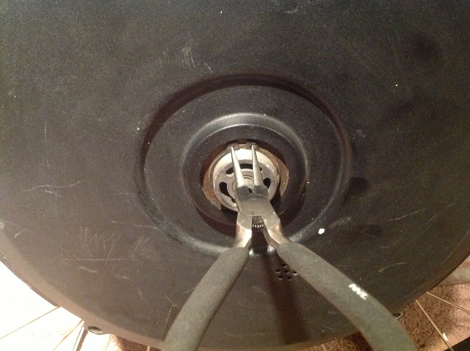
 The rear motor hub wheel with the freewheel and axle removed.

 Closer shot of the front battery hub.
 Closer shot of the rear motor wheel on the freewheel side

Front battery hub showing the connector side of the wheel

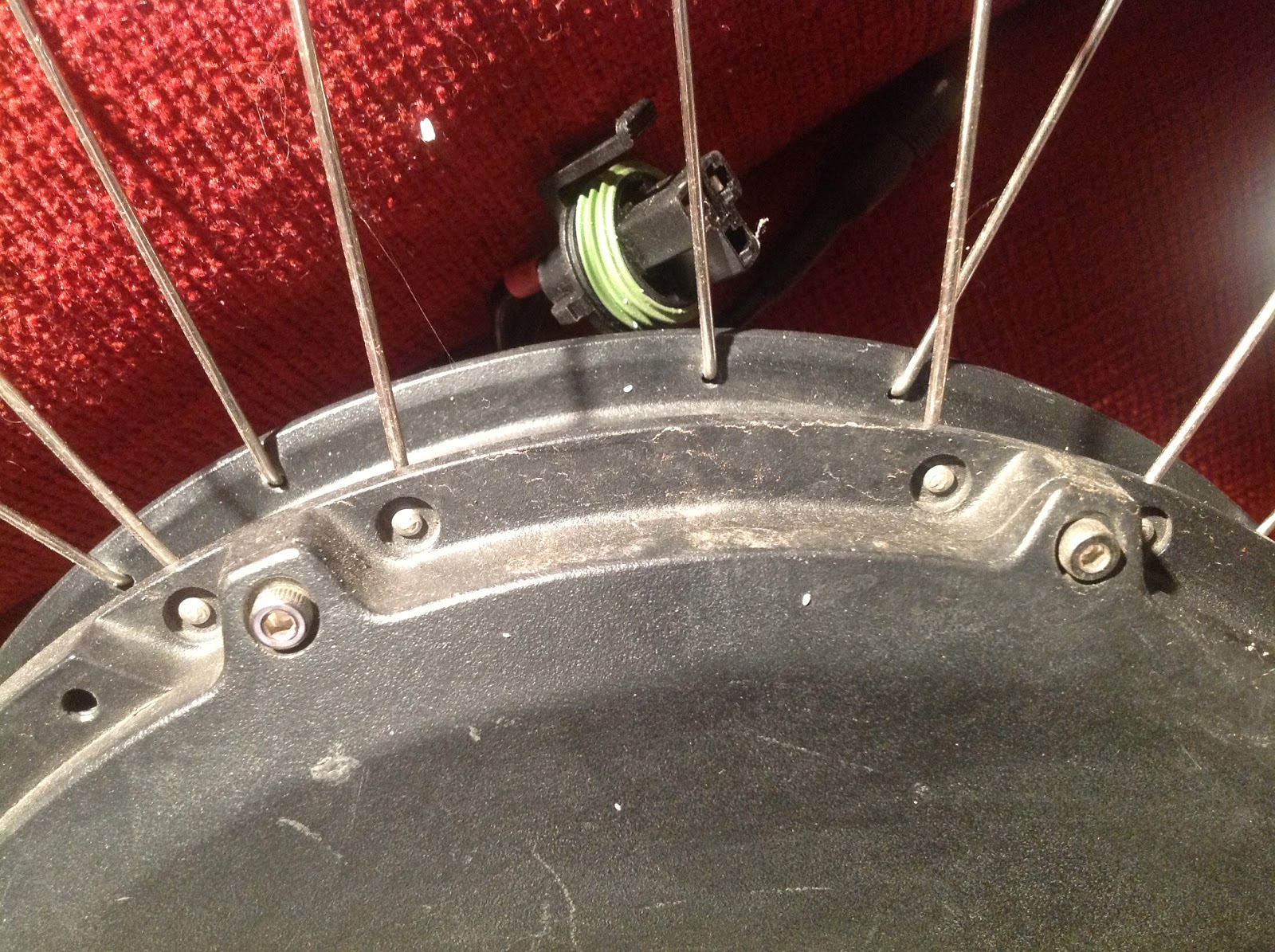
 Rear motor hub showing the disc brake mount and the connectors

 The two connectors on the rear motor wheel.

The wheels are truly very wide. They measure just over 1.5" wide on the outside.

 They measure just over 1.25" on the inside.

 The freewheel cassette. I need to reattach this somehow!

 The connectors from the ??? (I'm not sure where these go!)

The rat's nest of twist lock wires! I will definitely need to make these stronger and permanent once I get it working.

Here's the data connector going to the rat's nest.

Electrical wire nuts for quick connections.

 6-way Delphi connector

6-2ay Delphi connector other view.

eBrakes and throttle connectors.

Power connector using 2 way Delphi Metripacks

A 6-way Delphi connector using only 4 of the wires.

The non-functioning console with the bad LCD panel.

The small connectors for the console.

The clear window to the console from the inside showing the ribbon connector to the switches

Top view of the console window with switches.

The inside of the bottom half of the console.

The outside of the bottom half of the console showing the bike mount.

The circuit board of the console. Top view.


The circuitboard of the console. Bottom view.

Top view of the broken LCD panel.

Bottom view of the broken LCD.

Bike mount for the console.

The working console. Upside down.

The connector end of the console.

 The bottom view of the console showing the connectors and bike mount.
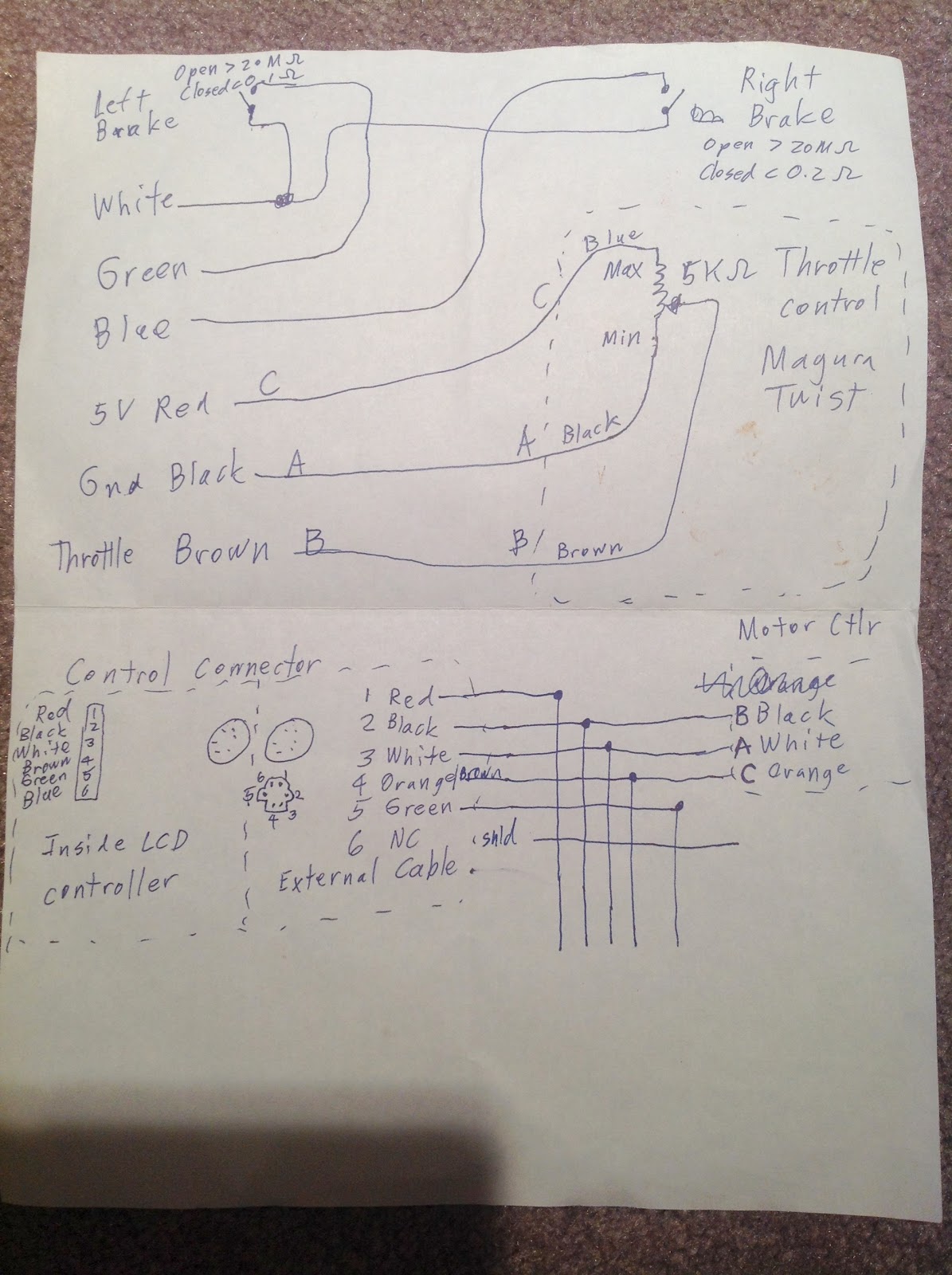
The schematic.

 The thumb throttle.

Thumb throttle showing a big "E" and "Maxi" under it.

Closer view of ebrake lever showing the wired switch.


3-way Delphi connector going into motor.

3-way Delphi connector.


Axle through-hole on the freewheel side.

Cabling going into motor.

Detail of the cover for the battery hub.

Detail of the spoke holes on the battery hub.

 There are these unused openings on the battery hub at 120° angles from each other. Wonder what they are?

Another detail of the battery spokes and cover screws.

Vent holes and keyed axle of the front hub.

Detail of the front axle on the connector side. 

Slight surface scratches. 
Valve opening in the wide front rim.

I'll do a detailed take-apart of the front battery and rear motor shortly. Hopefully this weekend if all goes well.