I thought these would be handy to charge 4.2V LiPO cells once in a while so I ordered a few. They are meant to charge 18650 sized cells but could easily be used for any LiPO cells. I used a wood dowel with two screws for battery contacts. That along with a couple of alligator clipped leads and you have a single cell LiPO charger!
Having identified the suspect group of Ping cells in my previous post, I thought I'd show how to unsolder a Ping cell group from the pack. As you could tell from the precious photos, the cell groups are heavily soldered together. The Ping cells have tabs for the +- terminals which are inserted through a small fiberglass circuit board with slots cut out for the tabs. There is an area of conductive material, probably tinned nickel on the fiberglass to provide an area to solder the tabs to. In order to remove the cells from the board, you'll need to remove most of the gloved up solder from the tabs and then life the terminal from the pad area and pull the tab out of the slot. All without burning yourself or your setup down! :-)
Here is a list of the tools I use.
An old Radio Shack 100W soldering gun.
A desoldering pump or what I call a solder sucker.
A "pig sticker" chisel or other 1/2" wide chisel
Flux
Solder wick
You need to carefully heat the tab area and use the solder sucker to remove as much of the solder as you can. This requires you to continually push the primer of the sucker down until it clicks and placing the tip near the solder gun tip and clicking the trigger to have the solder be sucked into the chamber of the sucker. You then prime the sucker again for the next shot. You will probably need to pull the cooled solder from the tip of the sucker after a successful extraction since the liquid solder will cool and form a small cylinder of solder which is ejected (mostly) from the tip when the pump is primed. You need to keep moving the solder gun tip since it is very hot and will damage the battery if left in one spot too long. After you've removed most of the solder, you then use your chisel to lift the battery tab from the pad area of the printed circuit board and then pull the battery down to extract it. It took close to 30 seconds for the solder gusto heat the solder tabs enough to liquefy the solder so be patient and work quickly. Remember tho move quickly and everything is very hot!
From left to right, solder sucker, flux, pig sticker, solder sick, extracted battery, soldering gun.
I took off the blue shrinkwrap as well as the multiple layers of black duct tape to get to the bare Ping 5Ah pouch cells. The voltages for the 8 groups of 4 cells each is:
1.39 3.34 3.34 3.38 3.34 3.34 3.35 3.28 You can probably tell which group is the problem and which group is puffed! :) Here are some photos of the innards.
\
Still with duct tape wrapping
Wire side revealed.
After removing multiple layers of duct tape and plastic wrap, the puffed cells are revealed on the + lead side. They measure 1.39V across the +- posts.
I ordered 3x3.7V 10Ah LiPO pouches to replace the defectives ones on my LiPO packs. They have markings on them that they are 37V and 10000mAh, however, the plastic sleeves are marked as being 3.7V and 1.4-1.7mOhm and ~3000 mAh. I wonder why the discrepancy. I'll test one tonight to see how it does...
I took a few minutes and soldered a set of JST-HX connectors to the 7S LIPO pack last night. The first cell in the pack is a bit low. I plan on charging it using a small single cell LiPO charger. Here's a picture of the Cell-log connected.
I don't plan on using the headlight as a typical headlight but as a flasher. The nice thing about the Grin Technology models is that they can be wired into virtually any system without a DC/DC converter and also that they remember what their setting was when you turned them off so they come back on in the same state! What a novel concept!
I took my newly configured Tidalforce S-750C bike out for a long ride on Saturday. It was a lovely day and I had worked on the bike Friday evening. I had to hook everything up including my old Bosch Fat Pack cells configured for a 2S3P configuration for 74V 6Ah. This motor rocks in a big way. Fast and fairly quiet, although it growled a bit at startup and lower speeds. Once you got up to around 15mph, the wind noise drowns out everything else. Top speed was 42.6mph and the range was 14.6 miles which is a great number for 6Ah of power.
It's divided into 3 parts. If you watch all three sections, You'll notice that I lost power twice. This is fairly easy to do when you have so many Anderson Powrepole connectors clipped together. If this were my final configuration, I would definitely tape all the connections together and secure the silicone wire so that it didn't try to pull the battery leads apart.
Here's a photo of the semi-final configuration of the bike with the Crystalyte HS3540 motor.
I installed the Ashima Airotor on the Crystalyte HS3540 motor last night. You can't really see the gold center portion very well and it looks a bit undersized for the job. I think I'm going to purchase a 200-203mm rotor to see if that fits the motor a bit better. I will need an adapter for the Avid BB5 so that it will fit with the larger rotor.
here is the Avid BB5 installed without the rotor on the motor.
Here's the rotor and Avid BB5 mounted.
Another angle of the Ashima Airotor 160mm with the gold center and the Avid BB5.
I needed a larger rotor for the Crystalyte motor so I ordered these on eBay. The gold toned one is the 160mm. Sorry about the fuzzy picture. The silver toned one is the 180mm. They were the most striking rotors I have seen in a while. I'll post more photos when I get some time.
I went to Fresh Bikes in Arlington today and saw this interesting vehicle parked outside. I was even more surprised to see that it was plugged into an outlet recharging!
I took apart the first of the defective 25.9V LiPO packs I got recently to try and see what was happening inside. If you just want to find out, then watch the video below. If you want to know the gory details then check out the pictures below the video.
First outer wrap of plastic and tape removed. Feline creature checks out the wiring.
What I thought was a dent in the outer casing of the pack was actually the first cell! This could be very dangerous if it should short out.
Close-up of the damaged cell.
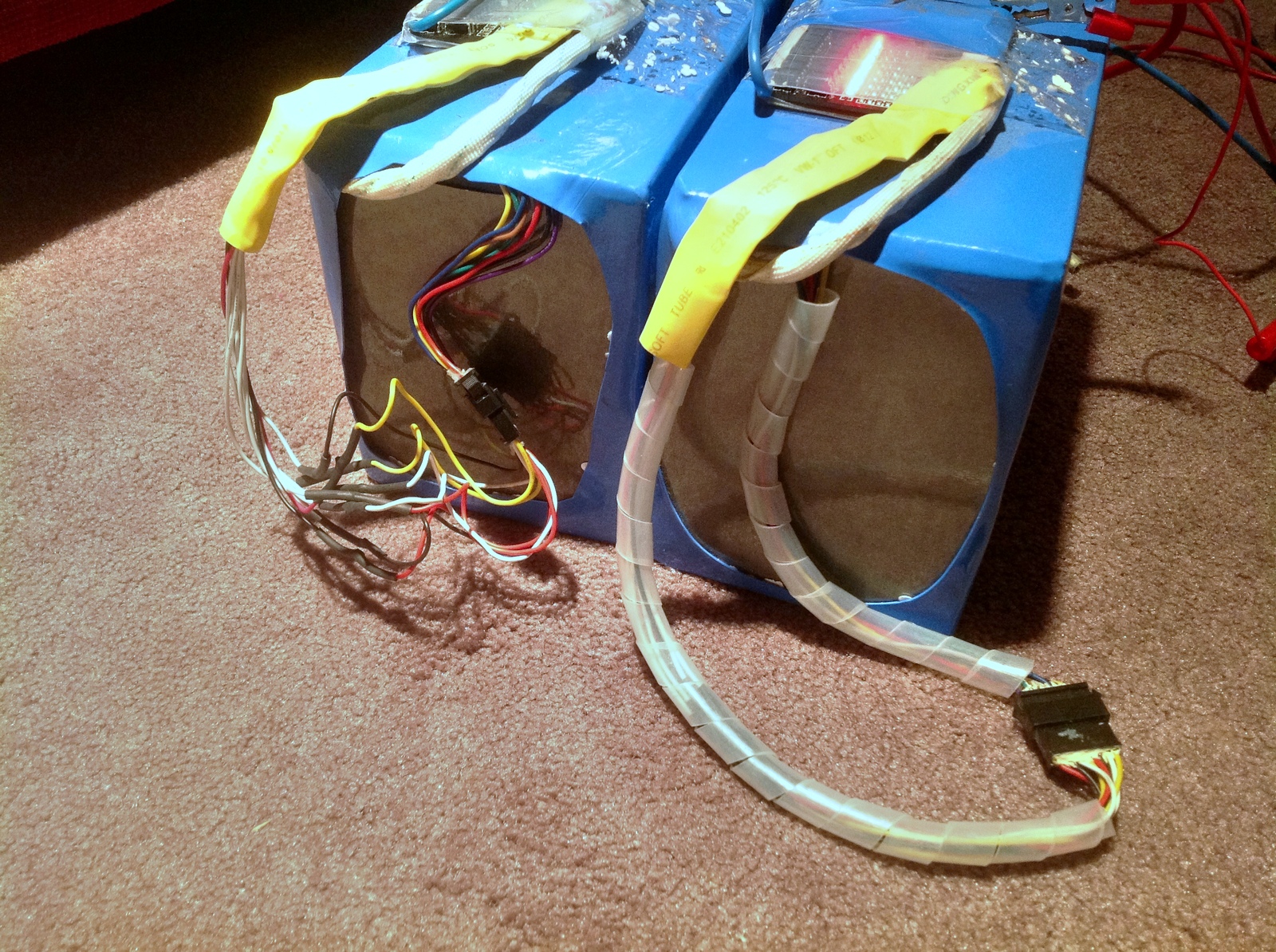
Close-up of the BMS with the individual leads going to the cells.
The BMS leads connected to each cell under the cargo tape.
Double-sided tape holds the BMS to the pack. You can also see the black plastic foam pieces separating the tabs.
The black foam pieces are supposed to hold the tabs in place to prevent them from shifting and shorting out.
The BMS leads are soldered to the tabs which are folded over each other and then soldered in series.
The solder quality isn't great. But it did seem to work.
You can see the globby look of the solder. It should be smooth and rounded.


 \
\